In Cleveland, the interface between glacial till and the underlying Ohio Shale creates a geotechnical conversation that few cities in the Midwest have to manage with such intensity. The Cuyahoga River valley and the Lake Erie shoreline have carved steep bluffs from Rocky River to Euclid, where relic landslides and slow creep movements are mapped in the surficial geology. When a developer or municipality encounters a cut slope exceeding 15 feet in these deposits, a slope stability analysis is not a formality—it is an engineering necessity driven by the Ohio Building Code and the site-specific groundwater regime. Our approach integrates laboratory shear strength data from the weathered shale with field observations of seepage zones, delivering a factor of safety that reflects actual pore pressure conditions rather than assumed drainage. This is especially critical where the deep excavations for underground parking or utility trenches unload the toe of an existing slope, triggering a mechanism that purely desktop modeling would miss.
A slope in weathered Ohio Shale can lose 30 percent of its static factor of safety during a spring thaw if perched groundwater is not identified and modeled explicitly.
Scope of work in Cleveland
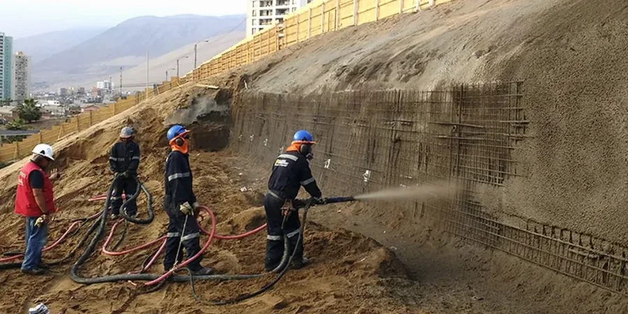
Typical technical challenges in Cleveland
IBC Chapter 18 and ASCE 7-16 require a minimum static factor of safety of 1.5 for slopes supporting structures, but the real risk in Cleveland lies in the progressive failure mechanism that develops in the desiccated shale zone. The Ohio Department of Transportation has documented multiple failures on Interstate 90 and Route 2 where cut slopes stood for 15 to 20 years before a wet winter triggered a translational slide along the bedrock contact. This delayed failure pattern is particularly dangerous because it falls outside the construction warranty period and outside the memory of the project team. Our analysis explicitly models the strain-softening behavior of the weathered shale using residual strength parameters, not peak values, for the portion of the failure surface that extends through the weathered zone. We also evaluate the effect of Lake Erie wave undercutting at the toe of coastal bluffs, applying a toe-erosion scenario that predicts retreat rates of 0.3 to 0.8 feet per year based on USGS lake-level records and the bluff stratigraphy.
Our services
A slope stability engagement in Cleveland draws on multiple geotechnical disciplines because the failure mechanisms in glacial stratigraphy are rarely governed by a single parameter. The following services are typically integrated into a single investigation and design package.
Limit Equilibrium and Finite Element Modeling
We use Spencer’s method and Morgenstern-Price for limit equilibrium in SLOPE/W, and PLAXIS 2D for finite element analysis when deformation predictions are needed. Both approaches are calibrated to site-specific pore pressure data from the Cleveland site.
In-Situ Shear Strength Testing
Cone penetration testing with pore pressure measurement (CPTu) provides continuous shear strength profiles in the soft clay and weathered shale, supplemented by field vane shear tests in saturated silt lenses.
Groundwater and Pore Pressure Monitoring
Vibrating-wire piezometers are installed in nested completions at the till-shale interface and within the shale fractures. Twelve months of data capture the seasonal response to snowmelt and lake-level fluctuations.
Remediation and Stabilization Design
When the factor of safety falls below code minimums, we design soil nail walls, anchored soldier pile systems, or drainage buttresses using parameters derived directly from the Cleveland subsurface investigation.
Quick answers
What is the expected cost range for a slope stability analysis in Cleveland?
For a typical Cleveland site with a single slope face and access for a track-mounted drill rig, the investigation and analysis package ranges from US$1,200 to US$4,300 depending on the number of borings, the depth of the weathered shale, and the instrumentation required. A site with multiple slope aspects or difficult access along the Cuyahoga valley may exceed this range.
How does the Ohio Shale affect slope stability differently than other bedrock in the Midwest?
Ohio Shale is a fissile, clay-rich Devonian formation that weathers to a low-plasticity clay with pronounced slickensides within the upper 10 to 15 feet. The residual friction angle can drop to 12–14 degrees along these polished surfaces, which is significantly lower than the intact shale and much lower than the limestone or sandstone bedrock encountered elsewhere in Ohio. This creates a preferential failure plane that must be identified during drilling and modeled with residual strength parameters.
Is a slope stability analysis required by the City of Cleveland for single-family residential construction?
The City of Cleveland Building Department typically requires a geotechnical report with a slope stability analysis for any proposed structure within 50 feet of the top of a slope steeper than 3H:1V, or where the slope height exceeds 10 feet. This is consistent with IBC Section 1805.3 and is enforced more stringently in the river valley neighborhoods such as Tremont and Ohio City, where historical landslide mapping exists.
Can vegetation and tree removal on a Cleveland slope trigger a stability failure?
Yes, and this is a common contributing factor in the eastern suburbs. Mature deciduous trees on Cleveland bluffs generate significant evapotranspiration that can lower the perched water table by 3 to 5 feet during the growing season. Removing the trees eliminates this suction, raises the phreatic surface, and reduces the effective stress along the failure plane. Our analysis models this scenario by running a no-root-cohesion, high-groundwater sensitivity case.